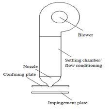
- Jet (spray)
- Sterilization plate
- Microphones
- Set of 32 filters
- Directed Wave tube
- Data acquisition system
- Power supply, battery and box regulation
- Loudspeaker
The panel of 1/4″ acrylic panel, it has three microphone arrays. Radial microphones are distributed along the radial line, 8 microphones are fitted with the equality of the distances between the plate and the glue. The other two compartments
were a small circle of microphones. The small circuit consists of 8 microphones with a 45⁰ angle between, while the large circuit consists of 16 microphones with 22.5⁰ between them.
Panasonic microphones were mono electret back capacitor microphone with a nominal sensitivity of -35 ± 4 dB, but this microphone was not calibrated individually, therefore,
one by one was calibrated and bandwidth 20-20,000 Hz. These microphones have a diameter pack of 6.35 mm, thickness 5 mm and a sensor diameter of 2 mm.
A set of 32 filters was created to run and condition the signals from the microphone arrays. Each channel contains a battery power source, the circuit was powered by a 9DC V power supply connected to the chain with a resistance of 2.2 k and, the two were combined in parallel with the microphone. The capacitor (C) and resistor (R2) form a high pass filter with a 0.16 Hz cutoff frequency, which was low enough.
The microphone calibration setting consists of a speaker installed on one end of the tube while the other is maintained. The speaker is used to generate flat sound waves where the travel is perpendicular to the axis of the tube. Only flat waves of sound frequencies are achieved with a wavelength longer than twice the length of the airway side. For a 30 mm square channel, this corresponds to frequencies below 5.8 kHz, which is high enough to cover the frequency of interest in the proposed experiments. The sound pressure and phase in a particular cross-section of the tube is uniform. Thus, by installing the signal microphone with a well-known frequency response in the tube wall facing the panel microphone, it will be possible to obtain the sensitivity and phase response of the microphone mounted in the same cross-section with respect to the signal microphone.
The data acquisition system has been used throughout experimental procedures such as wall pressure measurements, including the centering plate, calibrating microphones and obtaining data from 32 microphones.
A connection box is used to connect filters with data acquisition. The input ports were bank connectors, while the output ports were a parallel port. Parallel output is connected to another female parallel port connected to the data acquisition.
The power supply was used to run the filter set. Experiments have been performed to check the power supply. The electrical ground source is not connected. After connection to the electrical ground, low noise, however, the noise intensity was low enough to precede the experiments.
The wave generator was used to generate the sinusoidal wave with a certain frequency to calibrate the microphones.
The amplifier was used to amplify the output signal from the wave generator before the loudspeaker during the calibration microphones. The signal should be amplified because the output signal of the wave generator is weak to turn on the speaker.
The head receives amplification signal from the amplifier. Thus, the speaker stimulates the pre-defined sound wave to calibrate the microphones.
 Mechanical Engineering Department, National Research Centre Mechanical Engineering Department, National Research Centre